
Products
VCSEL
Vertical-cavity surface-emitting lasers, characterized and qualified in-house. This is the one area where we publish performance results and where product is available today.
Readout
Wavelength vs. temperature
The scale below is the wavelength axis itself: the fine dots are the scale, now sized to the band our devices actually occupy rather than a supplier catalogue. Characterized samples — etalon read at 791.5 nm, 25 µm mesa, 3 µm aperture — were swept on a WaveEye wavelength meter from 24.07 °C to 30 °C, moving 791.035 nm to 791.315 nm. The rubidium D1 line those atomic sensors need sits at 794.98 nm, marked as the target the tuning is aimed at.
Characterization and test
A laser is only as useful as the record that comes with it. Every die is probed on an automated test and scan setup built in-house, because the equipment to do it at the precision atomic sensing needs was not available to buy. That setup is what turns VCSEL characterization from a bench process into a repeatable one.
The same discipline runs through the rest of the work: parts are qualified before they leave, results are recorded per die rather than per batch, and what we publish about a part is what we measured on it. Detailed performance data is shared directly with customers evaluating a design-in.
A separate high-power multijunction line targets 905 nm and 940 nm for automotive applications, built and qualified on the same in-house test and scan setup.
Related
Metasurface work is developed alongside these devices. See Products for the wider set, or Capabilities for the systems this technology sits inside.
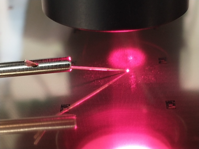
What the automated scan does
The probe head steps die to die across the wafer on a fixed pitch and records a result for each one before it moves. That is the difference between a characterization figure that describes a sample and one that describes a population — and it is why a part number here comes with a per-die record rather than a batch average.